A heavy duty apron feeder that can achieve smooth transmission, involving the conveying and transferring equipment of materials. The invention comprises: a drive shaft, a closed chain wound on the drive shaft and a tensioning shaft, and a chain roller supporting the chain: a drive chain link is arranged on both sides of each chain link assembly of the chain, and an industrial bearing plate is fixed in the middle, the drive chain link is connected with the industrial bearing plate, and the closed chain is engaged with the sprocket of the drive shaft by the drive chain link: The two ends of the tensioning shaft are installed at the corresponding position with the sprocket and the guide wheel engaged with the chain: the chain roller is arranged in five columns along the equipment, the outer two are the drive chain roller with the guard side, arranged under the drive chain section, the middle three are the smooth bearing chain roller, arranged under the supporting type bearing plate. The invention effectively solves the problems of shock vibration and deviation of the chain in the transmission process, reduces the wear of the chain, prolongs the operation cycle, and improves the production efficiency of the equipment.

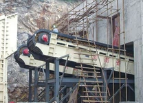
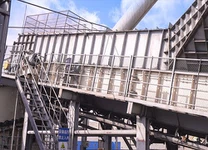
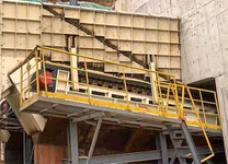
The ore from the mining face falls to the heavy duty apron feeder through the chute and is transferred to the special conveying equipment of the mine. heavy duty apron feeder is the key link between mining and beneficiation system, and is the throat equipment in mine production. heavy duty apron feeder is installed in the lower part of the chute, because the depth of the chute is generally 300-600m, and the chute is often filled with ore, so the equipment should not only withstand the huge pressure of the ore in the chute, but also resist the serious wear caused by the ore in the chute. Its working environment is very harsh: therefore, the equipment must have very high reliability, simple maintenance and small maintenance, easy replacement of wearing parts and so on.
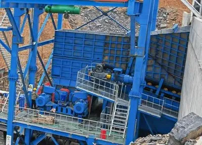
The structure of the prior art heavy duty apron feeder is composed of a closed chain wound on the drive shaft and tensioning shaft, the material falls into and is stacked on the tatted chain, and relies on the sprocket on the drive shaft to flick the chain wound on the drive shaft to rotate in a single direction, driving the chain movement to complete the conveying and transferring of materials. The weight of the material and the chain is supported by the chain roller under the area of the chain plate bearing the material. Due to the limitation of the structure size, the distance between the chain roller is greater than the pitch of the chain, and the chain is horizontal at the support point of the chain roller when the chain is running. The chain in the middle of the two chain rollers droop a certain distance due to the heavy weight of the material above and the limited tension of the chain, so that the chain is distributed in the bearing section in wave mode. In the process of transmission, the impact load will be generated, which will cause premature damage to the chain and chain roller. The disadvantages of the prior art heavy duty apron feeder are as follows:
1, the transmission is not smooth, easy to produce impact and vibration;
2, easy to wear, maintenance and overhaul workload, high labor intensity;
3, the chain is easy to run off, and sometimes it also touches the equipment pillar and foundation, and the chain is seriously worn.
To solve the above problems, we provide a kind of heavy duty apron feeder that can realize smooth transmission, effectively solve the impact vibration and deviation of the chain in the transmission process, reduce the chain wear, extend the operation cycle, and improve the production efficiency of the equipment. A heavy duty apron feeder for smooth transmission comprises: a drive shaft with a sprocket mounted in a fixed axial position, a closed chain wrapped around the drive shaft and a tensioning shaft connected by a number of link assemblies with pins, and a chain roller supporting the chain , characterized by: The two sides of each chain component of the chain are arranged with a drive chain section, and the middle is fixed with an industrial bearing plate, the drive chain section and the industrial bearing plate are connected with bolts, and the closed chain is engaged by the drive chain section and the sprocket of the drive shaft; At both ends of the tensioning shaft, a guide wheel engaged with the chain is installed at the corresponding position with the sprocket; The supporting roller is arranged in five rows along the equipment lengthwise. The outer two are the driving chain supporting rollers with guard edges, which are arranged under the driving chain link, and the middle three are the smooth bearing chain supporting rollers, which are arranged under the supporting type bearing plate. The three columns of the bearing chain rollers are staggered, and the middle column is coaxial with the roller with the retaining edge, and the two columns on both sides are coaxial.