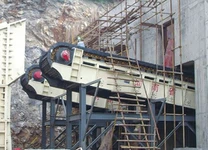
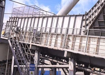
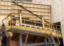
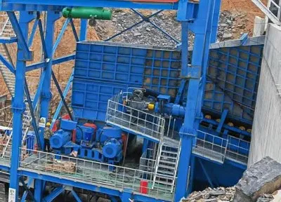
The company's limestone crushing and conveying system adopts mobile crushing station, which adopts metal structural frame from limestone silo to crusher foundation, and the ore bin capacity is about 45t. In the process of production, the ore is poured into the bin by Steyer dump truck and directly impacted on the back of the heavy duty apron feeder, resulting in the deformation of the supporting beam at the back, the steel plate of the slide rail connection is cut, the slide rail is deformed, and the equipment cannot be started with heavy load. Clearing the load for the equipment to start, not only affects the normal production operations, but also consumes a lot of manpower and material resources, therefore, can not reload the problem of starting, must be solved in time.
2 Cause Analysis
Because the limestone silo is too small and the length of the rear wall of the silo is too short, at the beginning of daily production, the ore mountain white unloading truck is poured into the silo, and the direct impact is on the back of the heavy duty apron feeder. In the continuous production process of 迮, although there is some material and stone at the back, it is generally thin and cannot form an effective natural pressure arch. When the ore is poured into the bin, the back also has to bear a greater impact. Therefore, in long-term production, the chain plate produces: slight deformation, the chain roller basically does not bear pressure: in the area of bearing the impact, the weld of the I-beam supporting beam and the slide rail is split, forming a gap, and the supporting role is not available: the slide rail connecting steel plate is cut, the slide rail bending deformation, forming the collapse of the impact area of heavy duty apron feeder. This permanent deformation, in the case of heavy load, the heavy duty apron feeder is already insufficient start-up capacity is even more stretched.

3 Take Measures
To solve the problem of frame deformation and heavy load can not start, three measures should be taken: first, reduce the impact of ore on the plate limit machine; The second is to enhance their anti-impact ability; The third is to check the starting ability of the heavy duty apron feeder main motor, if its starting ability is not enough, choose the motor that can meet the heavy load starting requirements.
3.1 It is impossible to increase the capacity of the silo and extend the length of the rear wall of the silo by reducing the impact of ore on the heavy duty apron feeder under site conditions. If the anti-impact frame is set up in the bunker, it is necessary to reduce the dip Angle after the bunker, so that the ore impact resistance frame after sliding into the bunker, after calculation and test, the dip Angle of the rear wall of the bunker needs to be reduced from 70° to 45°, which not only reduces the already small volume of the bunker, but also makes the ore slide down, it can be seen that the anti-impact frame is not feasible.
In order not to affect the production, the impact of Yeneng Cheng small ore on the plate limit machine, the workshop has formulated the measures that the ore material size of the human bin is less than 800mm, and the thickness of the material layer at the rear of the heavy duty apron feeder is ensured to be above 1 meter, and it is required to be strictly implemented in the production process.
3.2 Enhanced impact resistance
3.2.1 Improve the impact resistance of the rear support beams Remove the deformed 4 sets of 8 I-beams of model 20a at the rear of the heavy duty apron feeder and replace them with 15 I-beams of model 20a. I-steel models and parameters are shown in Table 1. The Type 206 I-beam has a greater bearing capacity than the type 20a T-beam. Under the same impact force, the impact force of each I-steel is half of the original, and the number of I-steel to withstand the impact has increased by about double. By replacing and increasing the type and number of I-beam support beams, the impact resistance has been increased by more than 3 times.
3.2.2 Improve Impact resistance of heavy duty apron feeder rear slide Remove the deformed 32a I-rail and replace it with a strengthened 32b I-rail. See Table 1 for the comparison of parameters of I-steel of two specifications. As can be seen from Table 1, 32b has greater impact resistance than 32a. The original connection part of the slide was in the impact area at the back of the heavy duty apron feeder, but in this technical change, the connection part is placed in the non-impact area at the front of the slide. The original splints of each slide rail used two 420x260×10 ordinary steel plates, in this technical change, the use of two 420x260x20 30Mn steel plates. M30x80 high strength bolts are used to secure the splint. After fastening the bolts and nuts, the electric solder joints are dead to prevent loose in the production process. Through the above measures, it has greatly enhanced its own strength and improved its impact resistance.