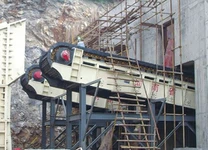
The heavy duty apron feeder specification is expressed as the width of the feeding trough (or tray). Each width has several side plate (or bucket) heights to adapt to different throughput requirements. As the height increases, the inclination coefficient increases. In addition to meeting the conveying capacity requirements, the width of the conveyor groove (or bucket) is also related to the specifications of the upstream feeding equipment (such as the cooling machine), and attention should be paid to the matching between the two to meet the uniformity of the width direction of the cloth. The selection of conveying groove (or bucket) height must meet the requirements of easy fabric, stable movement of running parts, and easy unloading of materials in the bending arc section, which is related to the chain pitch, width, bending arc radius, etc., generally 200~400mm, in the case of meeting the throughput, the preference is to use small width and large height apron feeder. The general relationship between clinker apron feeder specifications and kiln output is shown in Table 2. apron feeder traction chains are generally sleeve roller chains or forged chains. apron feeder specifications more than 630mm, the use of double chain, 630mm below, can be used single chain. The main parameters of the chain are pitch and breaking load. The commonly used chain pitch is 250 and 315, according to the actual maximum tension of the chain, and then consider a certain safety factor, choose the chain with the appropriate breaking load. The number of sprocket teeth is generally odd, in order to improve the life of the sprocket, double cutting teeth are often used. The number of sprocket teeth is related to the load, conveying speed and smoothness of movement. In the case of conveying speed and pitch unchanged, the more teeth, the lower the sprocket speed, and the less meshing number of teeth per unit time. The thicker the teeth, the longer the life of the sprocket, but the torque of the sprocket shaft increases, and a reducer with a larger speed ratio must be selected, such as the first wheel 2=12.5 relative to Z=7.5, the speed ratio increases by about 60%. Head and tail wheel under different load and due to the large difference, based on the equivalent wear and economic reasons, head to tail wheel often have different gear combinations such as 12.5/7.5, 10.5/7.5, 8.5/7.5, etc.

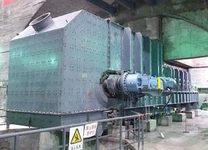
The function of a backstop is not the same as that of a brake. The backstop is set to prevent reversal; The brake is designed to slow down and hold the stop. For the backstop, the backstop automatically decreases when the system is restarted: for the brake, the heavy duty apron feeder will only continue to operate when the brake is manually removed. When inclined upward transmission, if the apron feeder can stop inertially due to sudden power failure or emergency stop, it is generally not necessary to set the brake, but because there are still materials in the bearing section, apron feeder will reverse, resulting in a car accident, so it is necessary to set the backstop. apron feeders commonly have roller overreach clutches and wedge overreach clutches, with the inner ring rotating and the outer ring fixed. The installation position of the backstop is: sprocket shaft (low speed shaft, ≤150 r/min), reducer intermediate shaft (medium speed shaft, 150-700 r/min) and the shaft connected to the motor shaft (high speed shaft, 700-3000rmin). From the perspective of safety and reliability, it is safest to set on the low-speed shaft, because the force system is shortest at this time, which can prevent the possibility of accidents when the rest of the shaft of the transmission system breaks the shaft, but the backstop torque is larger, and the backstop with larger specifications needs to be selected. When the backstop is set on the medium and high speed shaft, the force system is longer, the shafting between the backstop shaft and the sprocket shaft is stressed, and the safety is relatively poor, but the backstop torque is small, and the backstop with smaller specifications can be selected. In addition, when the backstop is set on the low-speed shaft, the sliding speed and sliding distance of the roller or the shaft are smaller, the wear of the roller or wedge and the raceway is relatively small, and the service life is longer.
The type and specification of apron feeder are determined according to the theoretical conveying capacity, conveying speed and dip Angle. Then, according to the process layout of heavy duty apron feeder (mainly apron feeder head and tail wheel horizontal projection length and conveying height), calculate the required shaft power and traction chain tension, select a chain with a certain safety factor, and configure the transmission system: Finally, according to the actual conveying speed determined by the transmission system and the weight of the running parts, the conveying capacity, shaft power and traction chain tension are calculated.