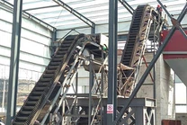
At present, in the conveying of bulk materials, especially sidewall belt conveyor, its main body is composed of the lower horizontal section frame, vertical or inclined lifting section frame, upper horizontal section frame, head frame, large dip belt and large dip belt driving device. Large dip Angle belt starts from the tail of the lower horizontal section, through the concave arc section, vertical or inclined lifting section, convex arc section, upper horizontal section and head frame, driving the material from the bottom to the conveyor. In the conveying process, due to vibration, material and the relative movement of the steering of the large dip Angle belt, as well as design, installation problems and other comprehensive problems caused by the material easy to fall down from the large dip Angle conveyor belt. General materials will be scattered in the upper horizontal section of the ground and the lower horizontal section of the ground, scattered in the upper horizontal section of the material is easier to deal with, through the ordinary scraper conveyor or other simple methods can make it back to the funnel, and the material falling on the lower horizontal section of the ground is generally by manual cleaning. This kind of manual cleaning workload is larger, and the working environment is quite bad, and the material can not return to the large dip belt in time, it will affect the throughput, and then affect the whole process system.

The purpose of the utility model is to overcome the above deficiencies and provide a type C feeding device which can effectively return all the materials dropped from the sidewall belt conveyor to the original big dip belt. The purpose of the utility model is as follows: a type C return device with sidewall belt conveyor, which is characterized by: The C-type material return device comprises a frame, a large dip belt device, covering belt device, feeding chute, head frame, tail frame and material collection groove, the frame is a "C" type structure, composed of the lower horizontal section, concave arc section, vertical or inclined lifting section, convex arc section and upper horizontal section end to end, tail frame is arranged in the lower horizontal section right end, the head frame is arranged in the upper horizontal section right end, The high inclination belt device comprises a tail frame guide roller, concave arc section to the inner guide roller, concave arc section to the outer guide roller, convex arc section to the inner guide roller, convex arc section to the outer guide roller, head frame guide roller, large inclination belt, transmission device and tightening device, the tail frame guide roller and tightening device is arranged on the tail frame, the tail frame guide roller is connected with the tightening device, Concave arc turning inner guide roller and concave arc turning outer guide roller an inside and an outside device are in the corner of the concave arc of the frame, convex arc turning inner guide roller and convex arc turning outer guide roller an inside and an outside device are in the corner of the convex arc of the frame, the head frame guide roller and the transmission device are in the head frame, and the head frame guide roller is connected with the transmission device. The high inclination belt is enclosed in turn around the tail frame guide roller, concave arc section to the inner guide roller, convex arc section to the inner guide roller, head frame guide roller, convex arc section to the outer guide roller and concave arc section to the outer guide roller, the sidewall belt conveyor covering belt device is arranged in the upper horizontal section of the frame. And placed under the horizontal section of the large dip belt, including the left guide roller, right guide roller and covering tape, the left guide roller and the convex arc of the large dip belt device to the inner guide roller coaxial installation, right guide roller fixed device in the frame head frame, and placed in the head frame guide roller lower left, the covering tape is closed around the left guide roller and right guide roller, And relative friction rotation with the large dip Angle belt in the upper horizontal section, the blanking chute downward is arranged at the bottom of the right end of the upper horizontal section of the frame, and the material collection groove is arranged upward on both sides of the lower horizontal section of the frame. The utility model realizes the flow of materials through the combination configuration of large dip belt and covering belt. The covering belt and the high Angle belt are rotated by relative friction. Between the horizontal section and the vertical or inclined lifting section under the high dip Angle belt, the inner and outer concave arc section is turned to the inner guide roller. Between the vertical or inclined lifting section and the upper horizontal section, the inner and outer convex arc section is turned to the inner guide roller. The sidewall belt conveyor head is fixed by the head frame guide roller. The tail frame guide roller and tensioning device are used to adjust the tightness of large Angle belt.